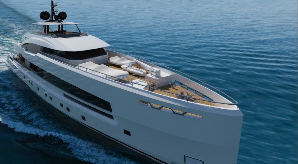
Продажа яхты YARA 44M ISA
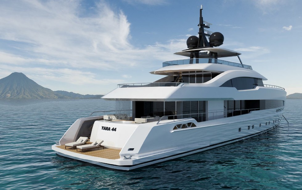
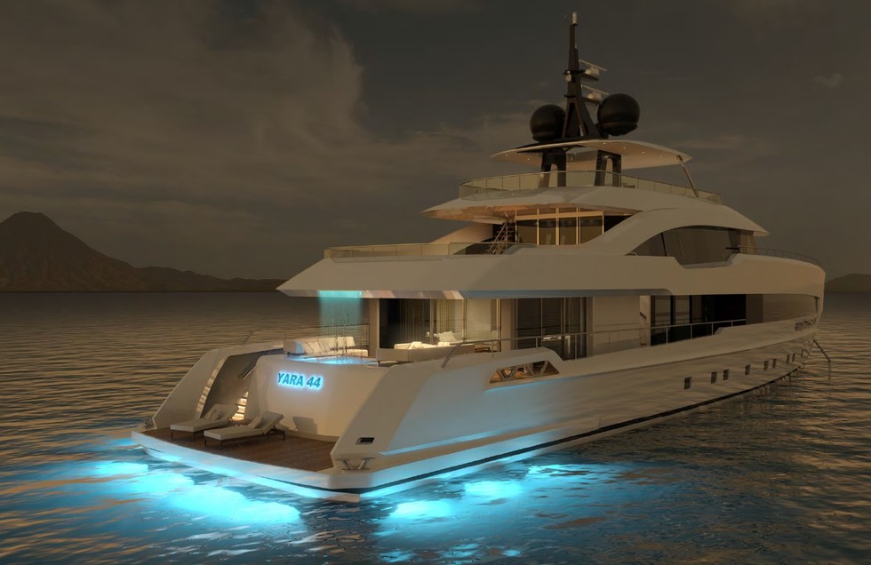
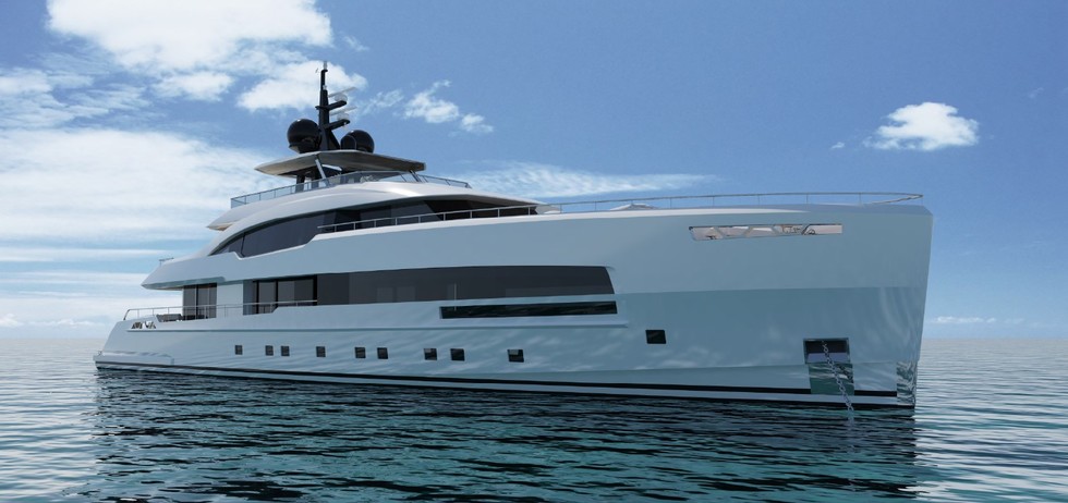
YARA 44M ISA
GENERAL DESCRIPTION
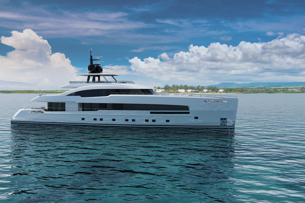
The yacht shall be of displacement type of steel construction for the hull and aluminium alloy construction for the superstructure, and fitted with two diesel engines operating fixed pitch propellers.
The Builder: ISA Group srl
Exterior Designer: Omega Architects
Interior Designer: To be defined
Naval Architecture: Van Oossanen b.v.
The yacht shall have four decks, from here called:
· “B” deck: Lower deck (or tank deck)
· “C” deck: Main deck
· “D” deck: Upper deck
· “E” deck: Sun deck
ARRANGEMENT
The complement of the vessel shall be as follows:
Owner's party:
· N. 1 Owner's suite
· N. 4 Guest cabins
Ship's complement
· N. 1 Captain’s cabin with one bed
· N. 4 Crew cabins with two beds each
MAIN CHARACTERISTICS
Except for the main dimensions, and wherever specified, the dimensions and volumes in this article are preliminary and remain to be verified and/or corrected by the Builder. Any machinery performance data reported in this article comes from the tables and data sheet provided by the manufacturer.
The speed values and the displacement below reported are referred to the final layout and equipment defined at the sign of the building agreement. The Builder shall inform the Owner of any deviation on speed and displacement, consequently to further Owner’s request during the construction of the vessel.
Tanks capacity
- Fuel oil tanks litres 44,000
- Dirty oil tank litres 1100
- New oil tank litres 600
- Fresh water tanks litres 14,500
- Grey/Black water tanks litres 6,800
- Sludge tank litres 2400
- Bilge tank litres 1,100
Main Engines
Two MTU 16V2000M94 each by max power of kW 1939 at 2450 rpm shall be supplied and fitted. Each engine shall be is couplet to a ZF gearbox.
Auxiliary engines
Two Kohler® diesel generators type by 100 KW 400 VAC 50 Hz at 1500 rpm ready for automatic parallel service shall be supplied and fitted.
Each of the main generators shall be capable to satisfy the ship necessities, under normal operation. In manoeuvring condition as well as in full hotel condition two generators will run thus working under automatic parallel.
Speed
The following conditions at the trial displacement of 295 tons (corresponding to 50% of the consumable) have been considered:
· maximum speed of 24.00 knots with M/E at 100% of MCR
· cruising speed of 19.00 knots with M/E at 50 % of MCR
Range
The range of the ship at the trial displacement will be as follows:
· 3900 miles at 13 knots
· 2900 miles at 16 knots
· 1950 miles at 19 knots
The range will be calculated on the basis of 37 tons of fuel (excluded umpumpable fuel) and one diesel generator running at 70% of the load.
HULL
The hull form shall be of bilge round type with level keel, good dead rise, transom stern and plumped shape bow and includes an integrated sprayrail in the forward one-third of the hull. The hull shall be also fitted with a skeg having adequate strength for docking purposes. The hull shall be built in aluminium alloy 5083-5086.
SUPERSTRUCTURE
The structure above the main hull deck shall be of sea water resistant aluminium alloy construction and shall include external and internal deck casings and decks.
GENERAL PAINTING
All preparation of surfaces and application of coating materials shall be made in accordance with product manufacturer’s recommendations instructions.
The hull top side and superstructure shall be faired and painted to Boero® or Awlgrip® system, with top coat colour at Owner’s choice.
AIR CONDITIONING
A Condaria® or equivalent air conditioning plant shall be realized with centralized units, suitable to provide the best efficiency for a vessel of this type.
In general all living quarters and interior spaces shall be provided with fan-coil units that receive their fresh air through fresh air units. All sanitary spaces shall be provided with forced exhaust ventilation.
The air conditioning system shall be designed and installed with the purpose of providing the maximum comfort of the guests and crew through the control of: temperature, humidity, air purity and velocity.
The plant shall de designed to meet the following ambient conditions:
Summer Outside Inside
Temperature dry bulb 34°C max 21° ± 1°C
Relative humidity 80% max 55% ± 5%
Sea water temperature 32°C max
Winter
Temperature dry bulb -3°C min 20° ± 1°C
Relative Humidity 85% max
Sea water temperature 4°C min
ANCHOR WINDLASSES
Two electrically driven vertical anchor windlasses made by Opem Sistemi® or equivalent complete with galvanised steel chain lifter and polished stainless steel warping head shall be provided.
WARPING CAPSTANS
Two electrically driven capstans made by Opem Sistemi® or equivalent with under deck motors and gear case and with a polished stainless steel warping head shall be fitted on the aft deck, on each side, on properly re-enforced seats.
STABILIZERS
One set of electro-hydraulic or fully electric driven non retractable type anti-rolling fins made by NAIAD® shall be provided. The fins construction shall be in steel and/or fiberglass.
BOW THRUSTER
A bow thruster unit shall be installed in a transverse tunnel in a suitable location in the stem forefoot.
The unit shall be manufactured by CMC Marine® and it shall be driven by an electric motor of 70 kW, turning a fixed pitch screw propeller.
STEERING GEAR
One Opem Systemi® electro-hydraulic and assisted steering gear shall be provided to allow the rudders to be drive by two hydraulic actuator cylinders, connected to the tillers.
Under normal condition, rudders can be controlled in the navigating bridge by follow up and non follow up steering modes and in the wings by non follow up steering mode. A non follow up steering mode shall be also foreseen in the garage area.
The emergency hydraulic steering shall be by the hand pump located into the aft garage.
STERN GANGWAY
One Motomar® or equivalent stern gangway electro hydraulic type shall be provided of suitable length but not less than 2,4 meters outside the stern platform. The ladder shall be of aluminium or stainless steel construction with teak treads, lighting and grating, portable stainless steel stanchions and rails.
INTERIOR OUTFITTING
The interior of the yacht shall be built in accordance with the Interior Decorator style and shall based on the premise that the design shall be of a common and uniform style in detail and construction throughout all areas. The exception being the crew area, which shall be somewhat simpler, none the less, no lowering standards of construction, plumbing, lighting or finish shall be accepted.
Any items necessary for the proper furnishing, outfitting and equipping of all spaces shall be selected in a manner to be suitable for the intended use. In the layout of the spaces and the various services, every possible advantage shall be taken of the available space and the various fittings are disposed and fitted in the most efficient manner. Fittings and items of equipment, which require ready access for operation or maintenance, shall be placed in positions so that access is secured without undue disturbance of other fittings in the immediate vicinity. Where it is necessary for maintenance of plant and concealed systems, secret detachable panels shall be installed.
TEAK DECK
Weather decks shall be sheathed with teak having the following finish thickness:
External weather decks: 16 mm on main deck and foredeck
16 mm on upper deck
16 mm on sun deck
Teak shall be of first quality and it shall be well laid out with margin planks and the planking following the curve of the gunwale and checked into a king plank.
ELECTRIC SYSTEM
The whole of the electrical installation shall be designed, installed and tested in accordance with the Classification Society requirements and shall be of a type proven satisfactory for marine use.
The installation shall be splash proof in the interior and totally waterproof at the exterior. All cables shall be numbered and marked on a proper drawing.
The performance/rating of electrical equipment that shall be determined on the basis of:
- Sea water temperature 32 °C
- Engine room ambient air temperature 45 °C
Consideration shall be given, in the selection of electrical/electronic equipment, to the ambient temperatures to be encountered when the yacht is not in use and without power. Care shall be taken with the selection and location of electrical equipment to ensure adequate protection against damage in service from water, steam, oil, humidity, vibration. Equipment should be arranged so as to facilitate easy access for maintenance.
SHORE POWER
The shore power shall run through EXENDIS modular frequency converter of 100 KVA installed in the engine room electrical space, with the following main characteristics:
Power 120 KVA / 96 kW
Input 1-3 phase, 180/520 VAC, 50-60 Hz
Output 3 phase, 400 VAC – 50 Hz
MACHINERY CONTROLS ALARMS AND INSTRUMENTATION
A Ship Alarm and Monitoring system shall be installed, consisting of:
· one main station on the bridge;
· one sub station in the engineer’s cabin;
· one sub station in the crew mess;
The system will also incorporate the power management system for the control and management of the diesel generators.
The system shall include:
· Up to fifteen programmed mimic screens, each displaying a specific
portion of the alarm/monitoring groups.
· Sufficient Data Acquisition Units, each with at least two unused incoming channels kept free for any retrofitting, located throughout the yacht to remain accessible, requiring the shortest possible cable runs.
The alarm system shall have its own network that shall be separate from the computer network and shall fulfil Class UMS notation requirements.
ELECTRONICS / ENTERTAINMENT SYSTEM
The perfect and organic integration of the systems that form the means of interface and control between the Owner, Guests and Crew represents the most important design principle of Entertainment, Communication, Security and Navigation systems.
This unified approach requires that the architecture of the main electronic system be based on network framework and cabling which are, as far as possible, shared. Integration is intended as:
§ effort to unify user interfaces;
§ TCP/IP units;
§ use of modular elements that can be assembled and connected in different ways to customize the system tailoring it to the Owner’s needs.
The fields to which this philosophy is applied are:
§ digital entertainment with top level displays, amplifiers and speakers;
§ full internet connectivity;
§ worldwide coverage for telephony and fax;
§ high level security and CCTV system;
§ home automation services (lights control, curtains control, HVAC control).
The following represent the general design rules applied for the selection of the main devices:
§ use of last-generation devices to have the most current model at time of delivery;
§ use of world wide distributed leader brands in the selection of devices in order to guarantee world-wide assistance.
CLASSIFICATION AND CERTIFICATION
The yacht, including its machinery, equipment and outfitting, will be constructed in accordance with the rules and regulations of Lloyd’s Regiter of Shipping for classification; the vessel shall meet all relevant statutory and classification requirements for a yacht of this type.
The following class notation shall be assigned:
X100 A1 SSC YACHT MONO G6, ● LMC, UMS
The yacht shall be also built for compliance with MCA LY3 Code for unrestricted navigation.